SYSTEM OVERVIEW
The DEEP THERMAL SHOCK SYSTEM is designed to allow the thermal cycling of up to four automotive engines one in each of four test rooms. The design allows for each room be able to perform up to two thermal cycles per hour. However, if not all four rooms are shocking, then more shocks per hour may be able to be performed in the active rooms. Two different temperature thermal shocks are provided for, one at -20°F (cold shock), and the other at a selected temperature between 0° to +120°F (warm shock). The cycles operate as follows:
DEEP THERMAL SHOCK (cold shock)
An engine is run for fifteen minutes on the "tower" cooling system. The coolant is warmed to the operating condition. At the end of the fifteen-minute period, the engine is stopped. The room's shock valves switch positions and coolant flow is transferred from the "tower" to the -20°F COLD TANK. The cold coolant chills the engine to -20°F and maintains it at this temperature for a fifteen-minute period while the engine is stopped. At the end of this fifteen-minute period the shock valves return to the "tower" flow position, the engine is restarted and the cycle begins again.
THERMAL SHOCK (warm shock)
An engine is run for ten minutes on the "tower" cooling system. The coolant is allowed to warm to a maximum of 240°F. At the end of the ten-minute period, the engine is stopped but motored by an exterior source. The room's shock valves switch positions and coolant flow is transferred from the "tower" to the room's HOT TANK. The coolant cools the engine to hot tank coolant temperature and maintains it at this temperature for a ten-minute period while the engine is being motored. At the end of this period, the shock valves return to the "tower" flow position, the engine is restarted and the cycle begins again. During this shock, the temperature of the hot tank may rise for a short period due to the addition of engine heat and the inability of the evaporator to remove all this heat.
EQUIPMENT
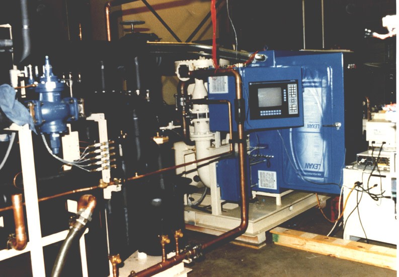
The operation of the system is controlled by the ALLEN BRADLEY 5/40 PLC and an ALLEN BRADLEY PANEL VIEW. The Panel View allows the manual starting and stopping of the system. Some of the system parameters may be adjusted. The Panel View will not allow access to the PLC control programs. A computer or programming terminal, with proper software, is required to access the PLC programs. A copy of the PLC programs and a hard copy printout of the programs are provided with the unit. Note: The individual room shock valves are not controlled by this PLC. The test room's PLC controls those valves.
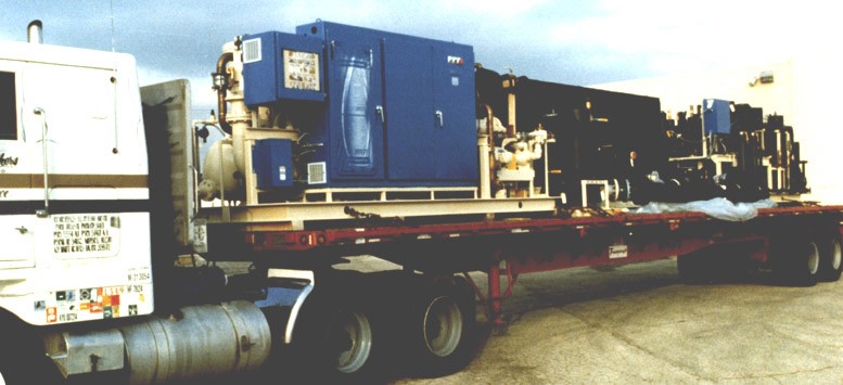
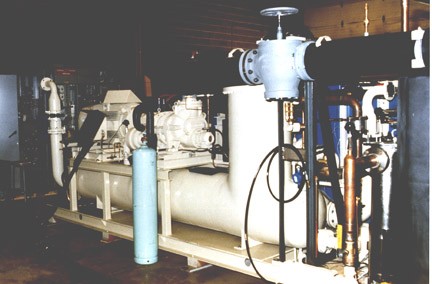
The REFRIGERATION that provides cooling for the shocks is furnished by a 300 horsepower water-cooled chiller system. This system is capable of providing 62.8 tons of refrigeration capacity at -40°F SST, and 105°F SDT. The cold tank and each of the room's hot tanks are provided with pumps and evaporators for cooling the glycol in these tanks. Each of these evaporators is capable of providing 12.5 ton of cooling to each tank at -40°F SET, and 105°F SDT. The cold tank temperature is set in the PLC program and you cannot adjust it at the PANEL VIEW. The hot tank temperatures for the warm shocks are individually adjustable at the PANEL VIEW between 0°F and 120°F
A VALVE RACK controls the glycol flow and direction for each individual room. These racks are mounted on the exterior walls of the rooms exhaust pits. The valve racks direct the flow of glycol to and from the engine, hot tank, evaporator, and cold tank. These valves, however, do not control the shock sequence of the engines. The valves that perform the shocks are controlled by the test room's PLC. The shock control valves are located after the valve racks.